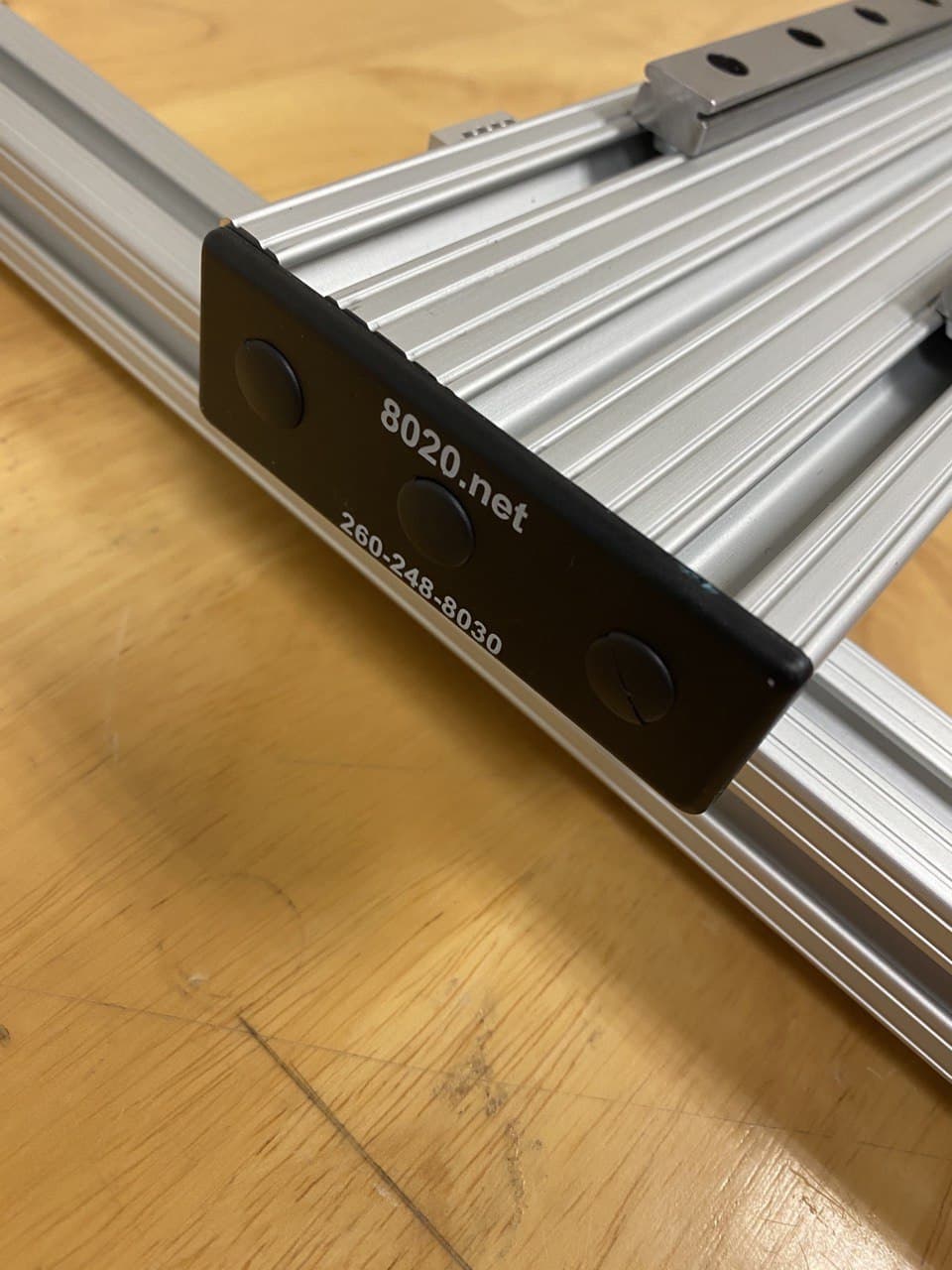
Sliding Rail
You can add a linear axis of motion to your Dorna 2 robot using the sliding rail kit and control it in synchronization with the robot using the Dorna Lab or Dorna 2 Python API. The sliding rail is offered as a partially assembled kit. In this document we will explain the assembly process of the rail and how to program it.
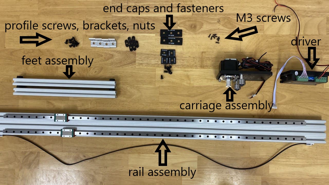
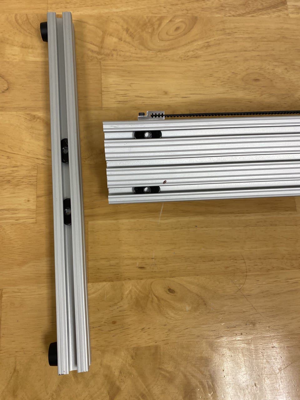
You will find the following items in your kit:
- Rail assembly
- Carriage assembly
- Driver
- Large end caps (x2), small end caps (x4), plastic screws (x8)
- Feet assembly (x2)
- T-nuts (x8), T-nut screws (x8), T-slot brackets (x4)
- M3 screws (x8)
Mechanical assembly
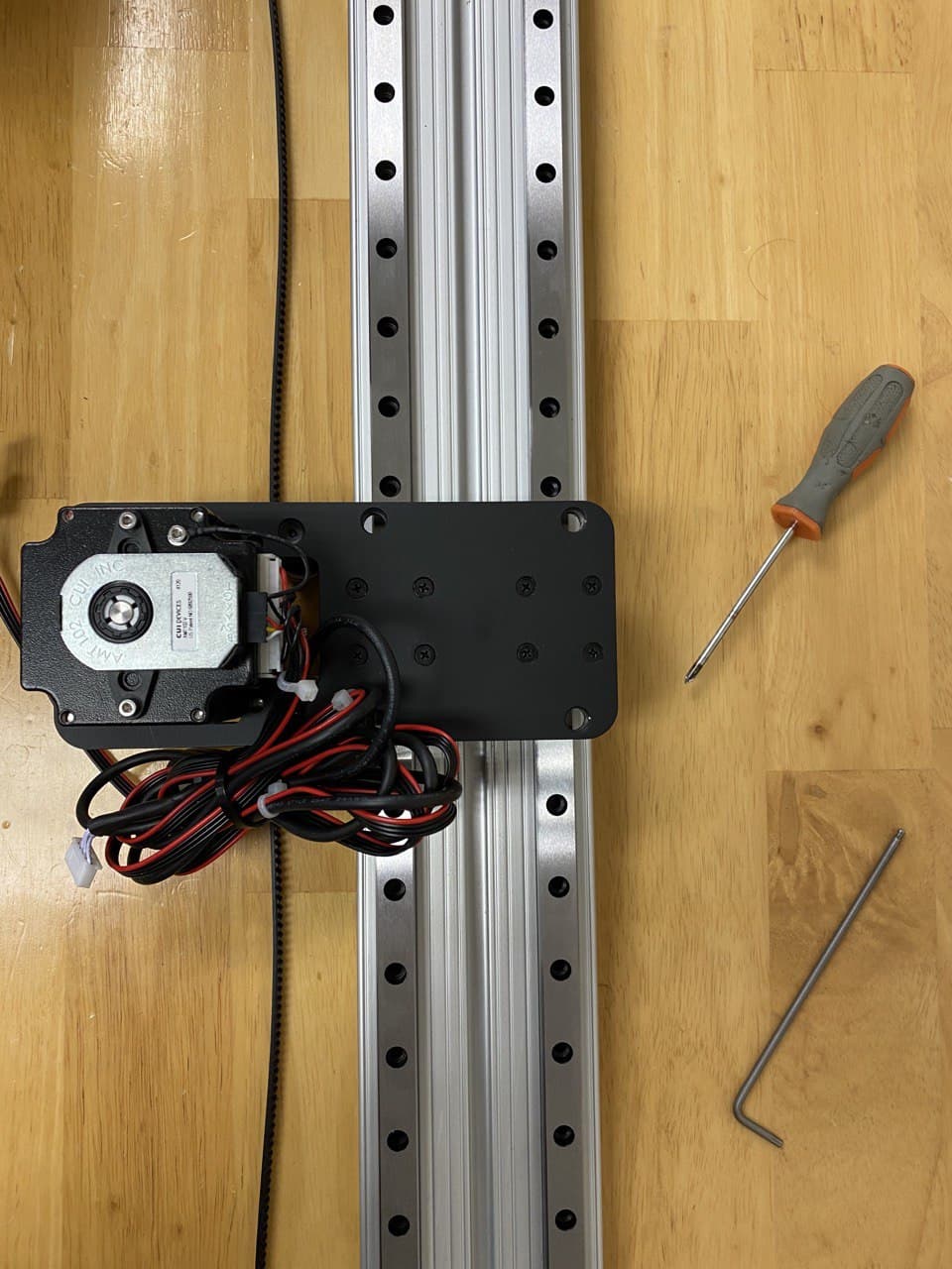
Carriage assembly
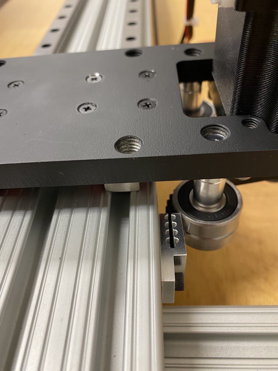
Use the 8 M3 screws to secure the carriage to the two bearing blocks on the rail. Start by fastening one screw from each bearing first and make sure that after fastening each screw the carriage can move along the rail without much resistance. Then, move on to the second screw from each bearing and so on. If at each stage the carriage is experiencing resistance, loosen the screws from the last step and fasten them again. It usually takes one to two rounds of tightening the screws before all screws are in place and the carriage is moving with little force.
Be careful not to move the linear bearings beyond the rails as the balls inside the bearing will fall off.
After securing the carriage to the bearing, you might still not be able to move the carriage easily on the rail or you feel its motion is too bumpy. In that case, you can adjust the rails by moving the carriage close to the rail screws, two at a time, and first loosening and then tightening the screws. This method will relieve some of the stress in the rails and will smoothen the motion of the carriage on the rail.
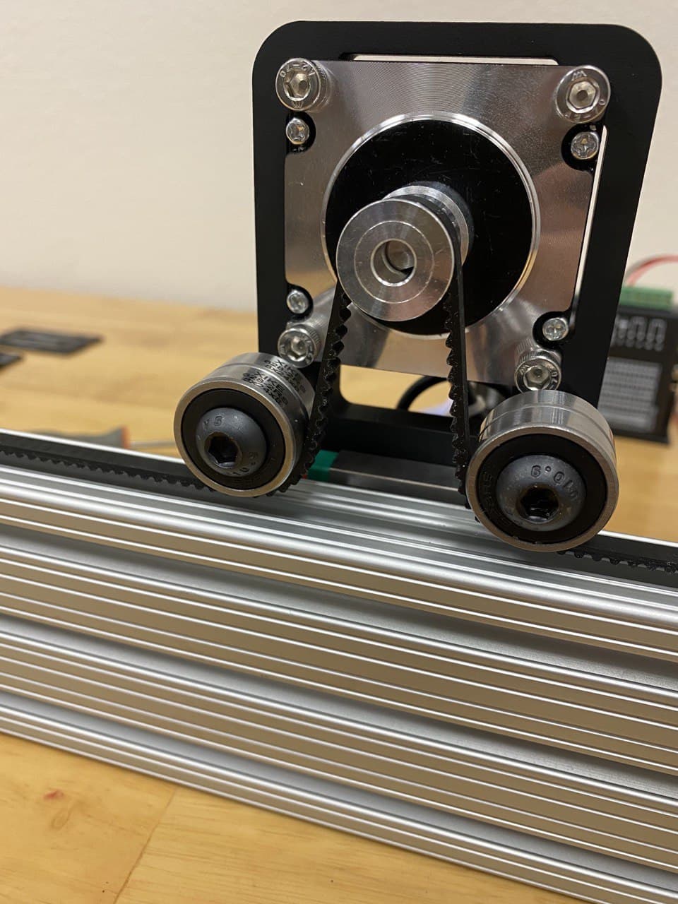
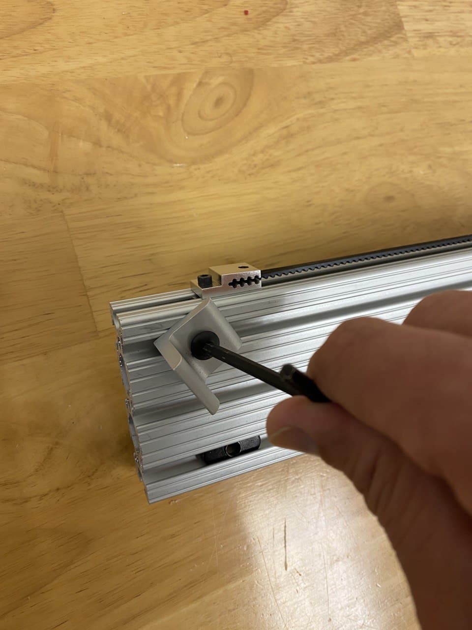
Belt installation
The belt is secured to the profile on both sides using belt clamps. We have already secured the belt on one side of the profile. Route the belt through the ball bearing idlers and timing pulley on the carriage motor and mount it on the other side of the profile while it is being tensioned.
The belt clamps also act as end stop, preventing the linear bearings from falling off on each side of the rail. Make sure the clamps are approximately at the same distance from each side of the rail.
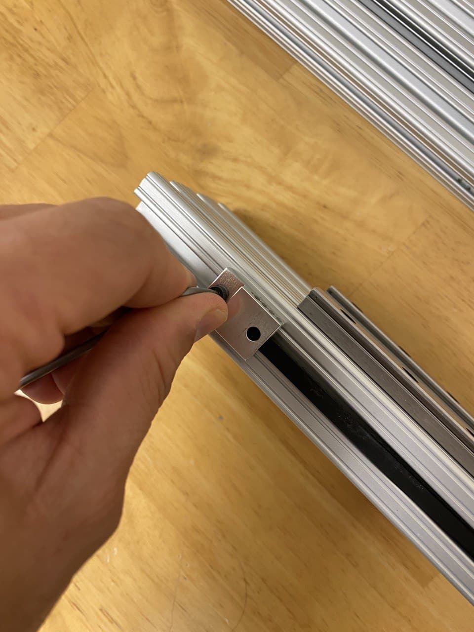
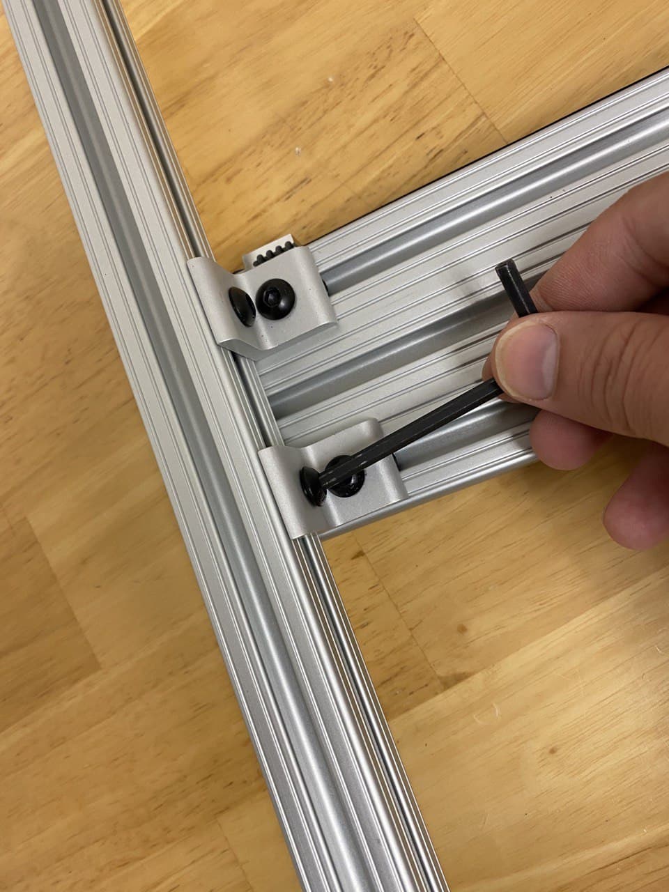
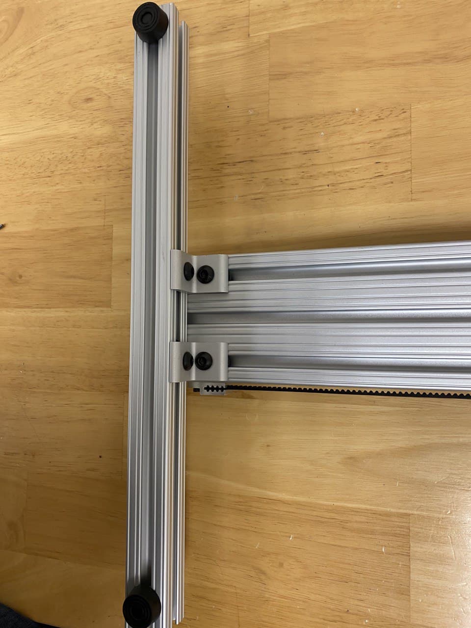
Feet installation
Next, slide in the Tnuts on each side of the main profile and on the feet profiles. Then use the Tnut brackets and M5 screws to secure the brackets to the nuts.
End caps
Finally, install the provided end caps at the end of the main profile and the two feet using the plastic fasteners.

Wiring
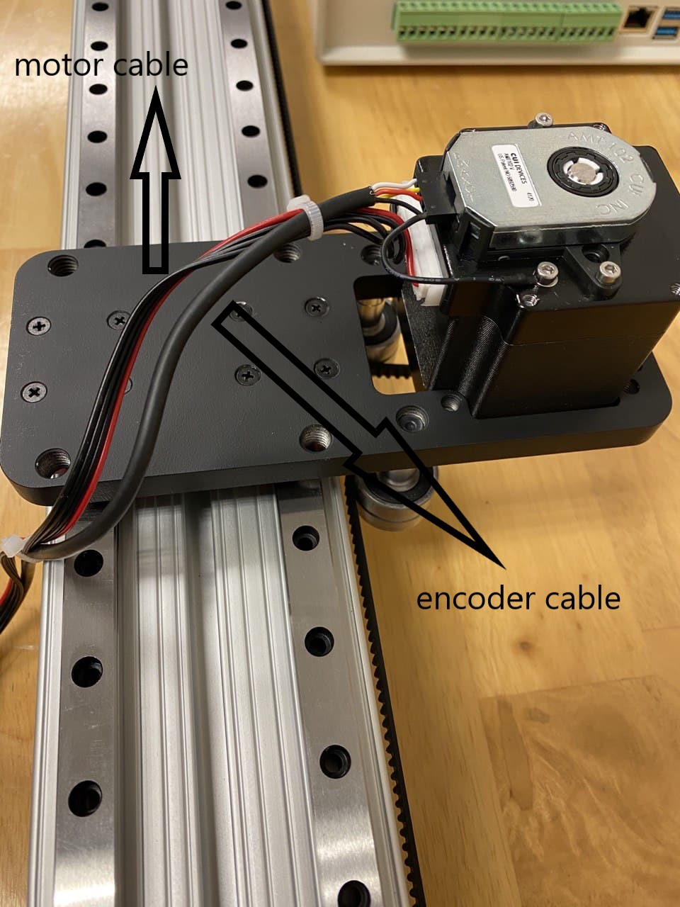
The motor on the carriage has two cables, one is the motor cable, and the other is the encoder cable.
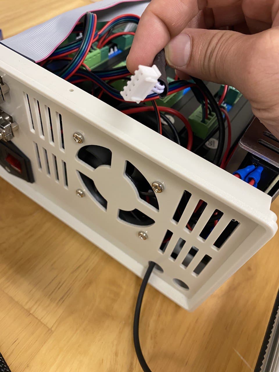
To install the encoder cable, first, open the controller box top panel, by removing eight screws on the sides of the top panel. Then route the encoder cable from one of the holes on the back panel and plug it into one of three available connectors for auxiliary encoders. Here we have chosen the 7th connectors for motor and encoder.
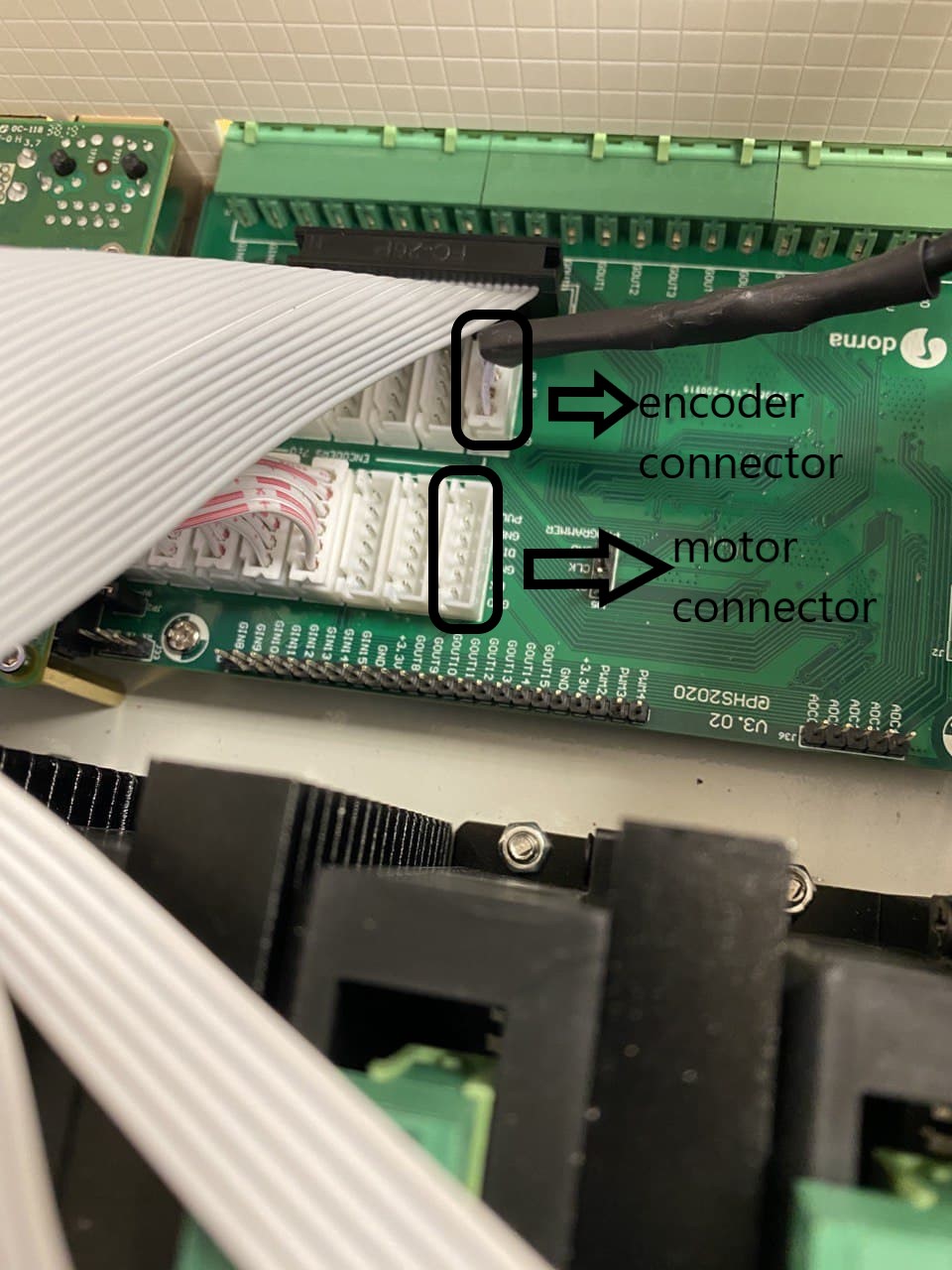
Next, place the motor driver inside the controller box, on top of the controller board and connect the driver six pin connector to the 7th motor connector on the board.
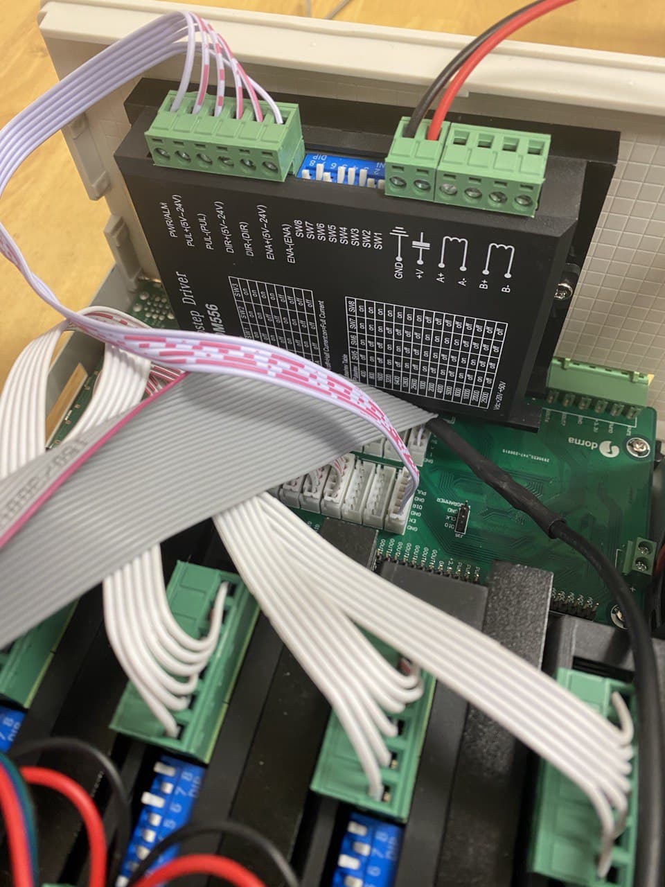
Next, you need to route the motor cable inside the controller box and connect it to the A+, A-, B+, B- connector on the driver.
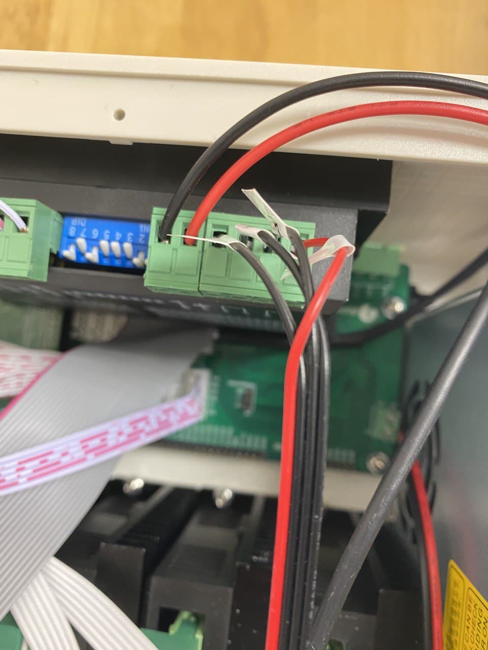
Finally, connect DC voltage pins on the driver to V- and V+ pins on the main power supply of the controller box. For that you will need to remove the power supply by removing the two screws that connect it to the bottom of the controller box.
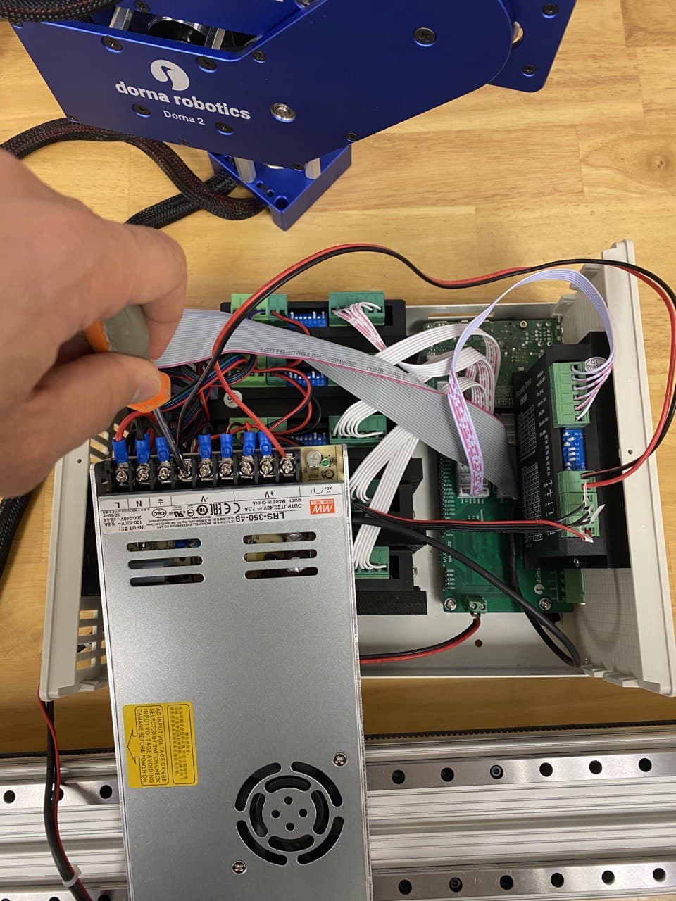
Now you can secure the power supply to the controller box and close the top panel of the controller box.
Make sure all power connections are completely turned off while working on the wiring of the robot or connecting any cable to the controller box. Otherwise, you might endanger yourself or cause permanent damage to the controller board.
Operation
Now that the rail is assembled and wired to the controller box, you can start operating it. You can operate the rail as an auxiliary joint with motion commands, jogging bottons, or set joint commands in Dorna lab or in Python API.
Each unit of joint corrsponding to the rail, is 2.4mm movement of the carriage on the rail.
You can use the right most end of the rail as zero position and set the rail joint to zero while it is at that end. Rail can travel up to about 400 units which corresponds to 960mm.
For more information on setting up the rail and programming it, please refer to the auxiliary axes document found here: https://doc.dorna.ai/docs/guides/auxiliary-axes/ .