Auxiliary axes
Dorna 2 enjoys an eight axes closed loop motion controller. Since the robot has five axes, the extra three axes are available for the user to use them with various automation applications, such as, linear track, camera zoom and focus control, round table, 3D printing nozzle head, etc.
In this document we will go over setting up and using the extra three axes of Dorna 2 robot which are also called auxiliary axes.
Basic properties
The three auxiliary axes of the controller are synched with the rest of the axes of the robot based on the trajectory of the motion. For line commands, they will vary based on the line trajectory and for cirlce commands, they will vary based on the circle trajectory.
Auxiliary axes, similar to main axes of the controller, are closed loop controlled. In a typical application, you can use stepper motors with differential encoders installed on them connected to the controller. The stepper motor and the encoder will need to satisfy the following requirements:
The encoder and the stepper motor driver should be compatible with 3.3 V voltage level.
The number of microsteps per turn of the stepper motor driver and the number of pulses generated in each turn by the encoder should be equal. For example, if the stepper driver is set to 4000 microsteps, the encoder should also be set to resolution of 4000 (which corresponds to
PPRsetting of 1000 on the encoder.)
One unit of motion of the auxiliary axes corresponds to 200 microsteps of the stepper motors. So if the stepper driver is set to 4000 microsteps per revolution, each 20 units of the auxiliary axes is one revolution of the stepper motor.
How to connect
To connect the encoder and stepper driver to the controller, you will need to remove the top panel of the controller box. Locate the controller board inside the box, and notice that there are 8 connectors for 8 stepper drivers on the board and 8. The first 5 connectors for stepper drivers and the first 5 connectors for encoders are reserved for the robot control. The user can use the last 3 connectors. The last 3 joints of the controller (auxiliary axes) are called j5, j6, j7 and are specified in the following picture.
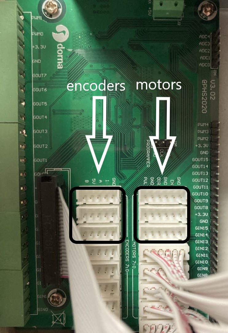
The encoder connectors are JST XH type with 5 pins which are respectively
B, VIN, A, I, GND.
The stepper driver connectors are JST XH type with 6 pins which are respectively
PUL, GND, DIR, GND, EN, GND.
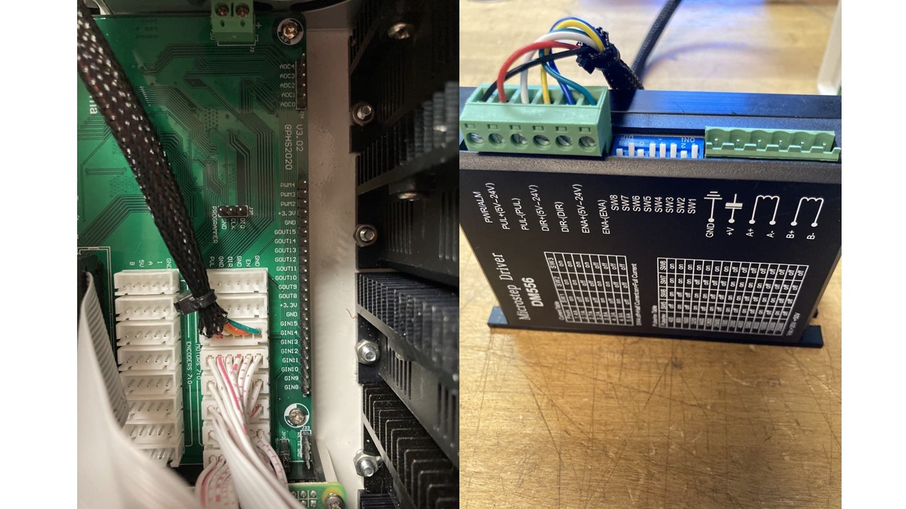
For instance to use the auxiliary axis j5, connect the stepper driver connector for j5 to your stepper driver. Make sure the same pins on the board and on the driver are connected together.
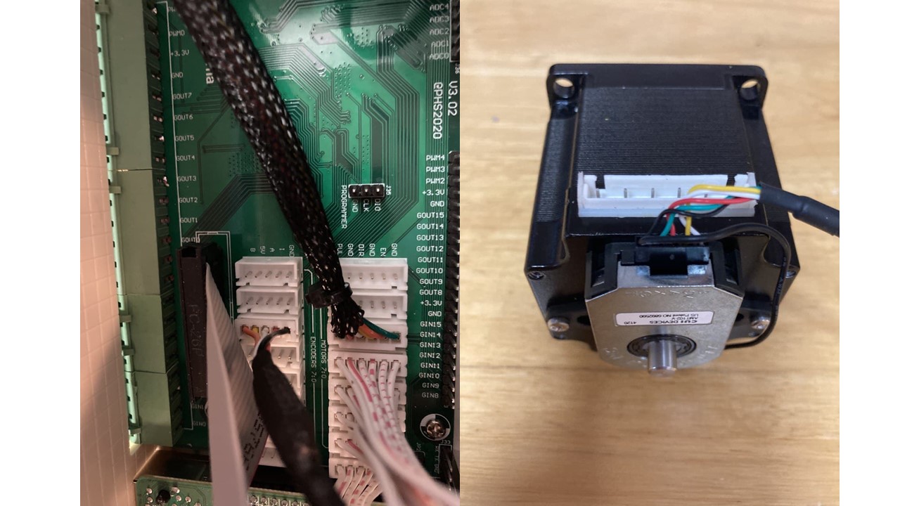
Next, install the differential encoder on the stepper motor. The encoder should have pins for A, B, GND, VIN and optionally index pin I. To protect encoder signal against motor noise the following are recommended:
- Use shielded cable for encoder connection to the controller.
- Connect
GNDpin of the encoder to the body of the stepper motor.
Now, connect the encoder connector on the board for j5 to the encoder. Again, be careful to connect the same pins on the encoder and board together. In case your encoder does not have an index pin, leave the I pin on the board disconnected.
Finally, complete the cabling by connecting the stepper driver to the appropriate power supply and also connect the A-,A+,B-,B+ pins from the stepper driver to the stepper motor.
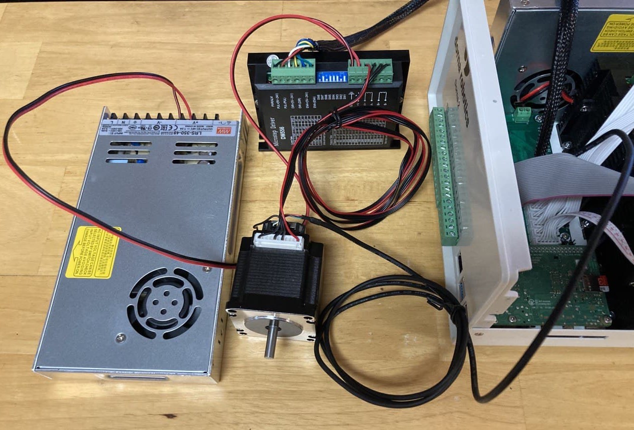
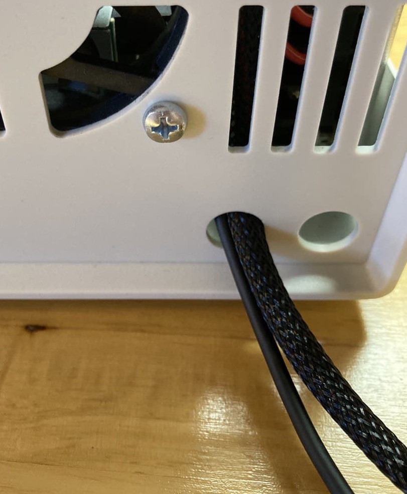
For better cable managment, you can use two holes placed on the back panel of the controller box.
As a reminder, set the microstepping on the stepper driver the same as the resolution of the encoder (resolution is four time
PPRvalue of the encoder).
Set the proper current setting on the stepper driver.
Now you can put the top panel back in place and turn the controller and the power supply on and start programming the the auxiliary axes.
Auxiliary axes in Dorna 2, Black version
The motors and encoders connectors for the three auxiliary axes in Black version of Dorna 2, are available on the back panel of the controller box. Therefore, in order to connect the motor driver and encoder to the controller board, you do not need to open the controller box and can directly connect them through the connectors on the back panel. In addition, the 48V and GND pins are available to power the driver directly from the controller box. The instructions for connecting the encoder and drivers wires can be seen at the end of the following video: https://youtu.be/FeDiU8BShk4
How to program
You can use Dorna lab or API to program the auxiliary axes the same way that you program the normal axes of the robot. For motion commands in joints space, the auxiliary axes are referred to as j5, j6, and j7. For motion commands in Cartesian space, the auxiliary axes are referred as c, d, and e respectively.
Auxiliary axes unit of distance is 200 microsteps.
For example, if you are using a belt driven linear rail that moves 10mm per turn of the motor, and the stepper driver is set to 4000 microsteps, then each unit of the auxiliary axes corresponds to 1/20 turn of the motor which is 0.5mm.
While programming, keep in mind that the maximum velocity of each auxiliary axes is approximately
500 unit/sec.
If the controller does not respond to the motion commands for the auxiliary axes (usually causing
alarmstate), the most probable cause is that the direction of the rotation of the motor and encoder are not consistent. The easiest fix for this problem is to change the wiring of the motor to the driver so that the motor rotates in the opposite direction. For that you can swipe the connection ofA+andA-on the driver (orB+andB-).